- Products
-
Shops
AI Search

Scope of Application
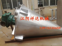
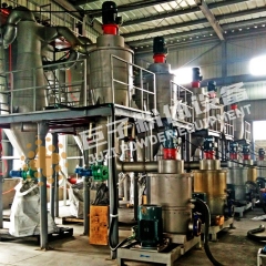
Double Spiral Cone MixerWidely used in industries such as chemical engineering, metallurgy, food, pharmaceuticals, fertilizers, coatings, pigments, dyes, pesticides, rubber feed, additives, refractory materials, fine chemicals, new materials, electronic plastics, ceramics, mining, and building materials for the combination of solids with "solids" (i.e., powder with powder), liquids with liquids, and powders with liquids. This machine has strong adaptability to mixed materials. It will not overheat heat-sensitive materials, will not crush or grind granular materials, will not cause stratification or segregation when mixing materials with significant density differences or varying particle sizes, and also performs well in mixing coarse, fine, and ultra-fine particles, as well as fibrous or flaky materials.
II. Working Principle
The rapid self-rotation of the two asymmetric spirals inside the mixer drum lifts the materials upward, forming two asymmetric spiral-shaped material flows moving from the bottom to the top along the drum wall. The rotational arm drives the spiral's planetary motion, causing materials outside the spirals to enter the spiral envelope to varying degrees. Some materials are lifted in a staggered manner, while others are thrown out of the spiral, thereby achieving continuous renewal of materials in the circumferential direction. The two material flows lifted to the top converge into the central concave area, forming a downward material flow that fills the voids at the bottom, thus creating a convective circulation. Due to the combination of the aforementioned movements, the materials achieve uniform mixing in a short period, resulting in high mixing precision.
III. Structural Characteristics
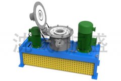
The double-helix conical mixer consists of a spray atomization device, a transmission part, a cover, spirals, a barrel, and a discharge valve.
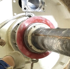
1Liquid Spray Atomization Device: The liquid spray atomization device consists of a rotary joint and a spray component. The spray component is fixed to the lower end cover of the distribution box using a flange, while the rotary joint and the spray component are connected movably to allow the rotary joint to be fixed onto the pipeline.
2. Transmission part: The motion from the rotation motor and revolution motor is adjusted to a reasonable speed through worm gears and gear sets, and then transmitted to the screw to achieve both rotation and revolution movements.
3. Lid Section: The lid supports the entire transmission assembly, which is secured to the lid with screws. The lid is equipped with a feed port, observation port, cleaning port, and maintenance hole.
4. Spiral section: When the two asymmetrically arranged spirals inside the cylinder undergo planetary motion of rotation and revolution, they turn over the material over a wide range, allowing the material to achieve uniform mixing quickly.
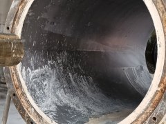
5. Cylinder section: The cylinder is of a conical structure, used for holding materials, ensuring fast, clean discharge without material accumulation or dead corners during unloading.
6Discharge Valve: The discharge valve is installed at the bottom of the cylinder to control material and discharge. This valve is available in three structural forms: manual, pneumatic, and electric. A liquid discharge valve (slurry valve) can be added based on user requirements.
Technical Parameters:
| Model
| 200 | 300 | 500 | 1000 | 1500 | 2000 | 3000 | 6000 | 10000 |
| Total volume (m3) | 0.2 | 0.3 | 0.5 | 1 | 1.5 | 2 | 3 | 6 | 10 |
| production volume (t/h) | 0.2 | 0.3 | 0.5- | 2 | 2 | 2.5 | 4 | 7 | 12 |
Rotational speed (r/min) | 143 | 143 | 143 | 57 | 57 | 57 | 57 | 53 | 53 |
Revolution speed (r/min) | 2 | 2 | 2 | 2 | 2 | 2 | 2 | 1.6 | 1.3 |
| Motor power (kw) | 3 | 3 | 3.5 | 5.2 | 5.2 | 7 | 8.7 | 18 | 29.5 |
| Mixed time (min) | 6~10 | 6~10 | 6~15 | 8~18 | 8~20 | 10~25 | 10~25 | 10~27 | 10~30 |
| External dimensions (Length × Width × Height) | 890 | 940 | 1142 | 1610 | 1636 | 1970 | 2210 | 3050 | 3050 |