- Products
-
Shops
AI Search

Product Introduction
I. Design Description of Vacuum Disc Dryer
1. Performance and Scope of Application
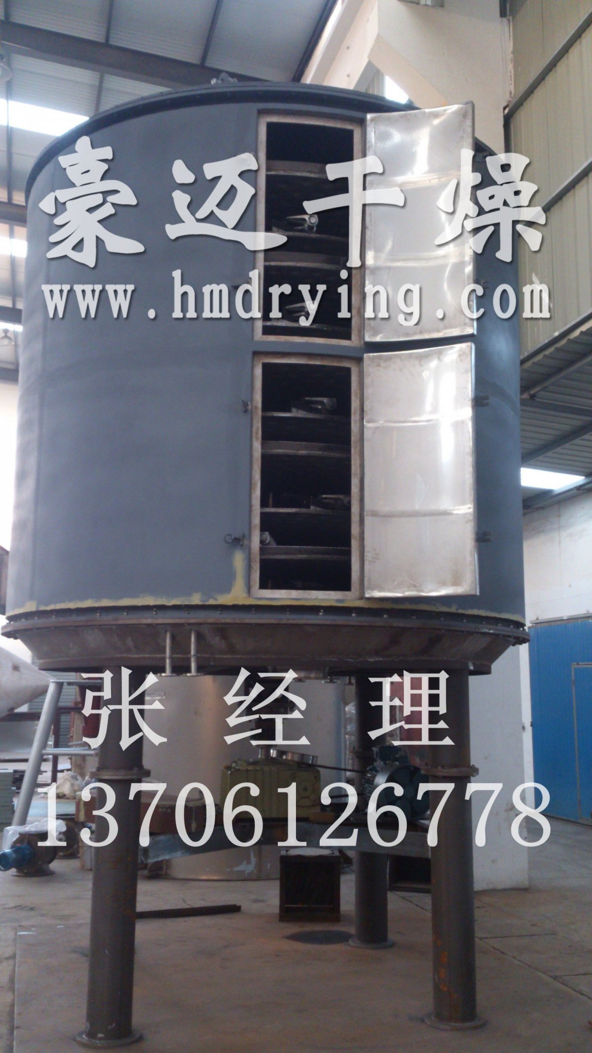
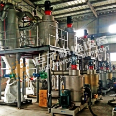
The vacuum disc continuous dryer designed and produced by our company is an efficient and energy-saving continuous drying equipment improved and innovated based on domestic and international technologies. Its unique structure and working principle determine its characteristics, such as high thermal efficiency, low energy consumption, small footprint, simple configuration, convenient operation and control, and a favorable operating environment. It is widely applicable for product drying operations in industries such as chemicals, pharmaceuticals, pesticides, feed, and new materials.
2. Working Principle and Process
Wet materials are continuously fed into the main hopper of the machine. The upper electric vacuum ball valve opens to alternately distribute the materials into the two top tanks. After that, the upper and lower vacuum ball valves of the tanks open and close alternately. Under the action of the stirring motor, the materials are continuously added to the **upper layer** of the drying disc in the dryer. The rabble arm equipped with rabble blades performs a rotary motion, causing the rabble blades to continuously turn and spread the materials, allowing them to fully absorb heat. The materials flow across the surface of the drying disc along an exponential spiral path. Materials on the small drying disc are transferred to the outer edge and fall from the outer edge onto the outer edge of the large drying disc below. Materials on the large drying disc move inward and fall from the central discharge opening into the lower small drying disc. The large and small drying discs are arranged alternately in an up-and-down pattern, allowing the materials to flow continuously through the entire dryer. The hollow drying discs are supplied with a heating medium. The heating medium enters the disc surface from one end of the drying disc and is discharged from the other end. The dried materials fall from the **last layer** of the drying disc onto the cooling bottom layer of the shell. Finally, they are moved by the rabble blades to the discharge port and discharged into the two bottom tanks. The discharge is carried out through the alternate opening and closing of the upper and lower electric vacuum ball valves. Moisture evaporates and escapes from the materials. It is forcibly extracted by the vacuum pump from the upper and lower tanks. The solvent is condensed in the condenser and recovered into the buffer tank, while the moisture is **finally** vented.
Vacuum Tray Dryer Process Suitable for drying heat-sensitive materials that require very low drying temperatures, such as pharmaceuticals, vitamins, biological products, enzymes, and solvent-containing materials. Wet materials are added in batches to a quantitative feeder capable of withstanding negative pressure. After starting the vacuum pump to create a negative pressure state in the tray dryer, the materials are evenly fed into the dryer through a continuous locking device for the drying operation. The dried materials are discharged from the outlet at the bottom of the dryer. The moisture escaping from the materials is recovered through a condenser and a solvent receiving tank. The entire operation is carried out under negative pressure.
II. Suitable materials for vacuum disc dryers:
The closed-loop solvent recovery disc continuous dryer process is suitable for drying processes that require solvent recovery, as well as for drying processes where the wet components are flammable, explosive, or toxic substances that cannot be directly discharged into the atmosphere and must undergo recovery treatment. Examples of such wet components include methanol, ethanol, gasoline, pyridine, petroleum ether, halogenated alkanes, acetone, formaldehyde, etc. Based on the basic configuration, continuous inlet and outlet locking devices, a condenser, a solvent receiving tank, and a vacuum pump are added. The wet components (solvent vapors) escaping from the dryer enter the solvent recovery condenser from the top of the dryer, where they are condensed into liquid solvent under the cooling effect of the cooling medium. The liquid solvent then flows into the solvent receiving tank, while non-condensable gases leave the solvent receiving tank and are discharged by the vacuum pump. The cooling medium should be selected as cooling water or chilled brine based on the characteristics of the solvent.
1 Wet Material 2 Quantitative Feeder 3 Continuous Ball Valve Feeding 4 Vacuum Disc Dryer 5 Condenser 6 Heating Medium Inlet 7 Heating Medium Outlet 8 Solvent Receiver 9 Vacuum Pump 10 Dry Product 11 Cooling Medium Inlet 12 Cooling Medium Inlet 13 Exhaust Gas Vent
III. Principle of Nitrogen Supplementation in Vacuum Tray Dryers:
The disc continuous drying process with nitrogen circulation protection is suitable for drying substances that are particularly prone to oxidation, highly flammable, explosive, and highly toxic. Based on the basic configuration, it is equipped with a solvent condenser, solvent receiving tank, inert gas circulation machine, fin heater, inert gas replenishment tank, and other equipment. The wet material is fed into the dryer through a quantitative feeder via a continuous lock, and it moves from top to bottom to complete the drying process. The dry material is discharged from the bottom of the dryer through a continuous lock, while the moisture evaporated from the material exits from the top of the dryer and enters the condenser, where it condenses into liquid and flows into the solvent receiving tank. The cooled inert gas is transported by the circulation machine back into the dryer, absorbs moisture from the material, and then re-enters the condenser for cooling, forming a closed-loop circulation. Before entering the dryer, the inert gas must be preheated by the fin heater, and the inert gas storage tank can replenish the nitrogen lost in the system.
IV. Unique Features of the Vacuum Disc Dryer
The material enters the feeding hopper 1, and pneumatic ball valves a and d open simultaneously, allowing the material in feeding hopper 1 to enter the feeding transition silo 1. At the same time, the material in feeding transition silo 2 enters the dryer under the action of the stirring device. Pneumatic ball valves a and d close simultaneously, while pneumatic ball valves b and c open simultaneously, allowing the material in feeding hopper 2 to enter the feeding transition silo 2. Meanwhile, the material in feeding transition silo 1 enters the dryer under the action of the stirring device. This process repeats, and the wet material continuously enters the top drying tray inside the dryer.
After drying, the material enters the inlet of pneumatic ball valve e under the action of the rake blade. Pneumatic ball valves e and h open simultaneously, allowing the dry material to enter the discharge transition hopper 1. The material in discharge transition hopper 2 is discharged out of the dryer through pneumatic ball valve h. Similarly, after drying, the material enters the inlet of pneumatic ball valve g under the action of the rake blade. Pneumatic ball valves g and f open simultaneously, allowing the dry material to enter the discharge transition hopper 2. The material in discharge transition hopper 1 is discharged out of the dryer through pneumatic ball valve h. This process repeats, and the dry material is continuously discharged out of the dryer for packaging.
Vacuum Disc Dryer Our company has applied for a patent**. Any unauthorized reproduction of this material will be pursued by the company. With extensive technical expertise and customer cases, our company specializes in the manufacturing and design of vacuum disc dryers. The vacuum disc dryer is suitable for drying solvent-containing materials, with the advantage of solvent recovery through condensers. Choose Haomai Drying for a worry-free experience.