- Products
-
Shops
AI Search

| Specifications | YGM65 model | YGM75 model | YGM85 model | YGM95 model | YGM130 model |
| Feed particle size (mm) | <30 | <30 | <30 | <30 | <30 |
| Product Particle Size (Mesh) | 0.613-0.033 (*as fine as 0.013) 30 mesh - 425 mesh, 1000 mesh | 0.95-0.015 (*Fine 0.013) 20 mesh - 800 mesh, 1000 mesh | |||
| Production range (tons, hours) | 0.25-2 | 0.28-3 | 0.35-3.4 | 3.5-5 | 5-12 |
| Grinding ring inner diameter (mm) | φ650 | φ780 | φ830 | φ950 | Φ1280 |
| Roller diameter (mm) | φ210 | φ260 | φ270 | φ370 | φ410 |
| Grinding Ring and Grinding Roller Height (mm) | 150 | 150 | 140 | 170 | 210 |
| Host motor model and power | Y200-8 -15kw | Y225G-8-18.5 kw | Y225M-8-22 kw | Y225S-4-37 kw | Y280S-4-75 kw |
| Fan motor model and power | Y160M-4 -11 kw | Y160L-4-15 kw | Y180M-4-18.5 kw | Y200L-4-30 kw | Y250M-4-75 kw |
| Analysis of Motor Model and Power | Y112M-6 -2.2 kw | Y112M-6-2.2 kw | Y180-4-2.2 kw | YCT200-4A-5.5 kw | YCT200-4B-7.5 kw |
| Total Power (kW) | 28.2 | 35.7 | 42.7 | 72.5 | 157.5 |
| Overall dimensions (meters) Length × Width × Height | 4.1×3.3 ×4.5 | 4.5×4.5×5.1 | 4.5×4.5×5.2 | 7.1×5.9×7.9 | 7.8x8.0x9.7 or 9.2x7.2x9.7 |
| Hoist motor | Y100L-4-3 kw | Y100L-4-3 kw | |||
| The motor of the jaw crusher | 200×300 Y132M-4-7.5 kw | 250×400 Y180L-6-15 kw | |||
| Electromagnetic Vibratory Feeder | GZ 1F 60 w | GZ2F 150w | |||
I. Uses of the High-Pressure Suspension Roller Mill:
This machine is mainly used for grinding and processing mineral products in industries such as metallurgy, building materials, chemical engineering, and mining. It can grind materials including quartz, feldspar, calcite, talc, barite, fluorite, rare earth, marble, ceramics, bauxite, manganese ore, iron ore, copper ore, phosphate rock, iron oxide red, zircon sand, slag, water slag, cement clinker, activated carbon, dolomite, granite, garnet, iron oxide yellow, soybean cake, fertilizer, compound fertilizer, coal ash, bituminous coal, coking coal, lignite, magnesite sand, chromium oxide green, gold ore, red mud, clay, kaolin, coke, coal gangue, porcelain clay, kyanite, fluorite, bentonite, maifan stone, rhyolite, greenstone, pyrophyllite, shale, purple sand stone, greenstone, layered rock, basalt, gypsum, graphite, silicon carbide, and other non-flammable and non-explosive mineral products with a Mohs hardness below 9.3 and moisture content below 6%.
II. Six Major Features of the Strong Pressure Suspension Roller Mill:
Compared with other mills, the output increases by 20-30% under the same power conditions, and the grinding pressure of the roller on the material is increased by 800-1200 kg under the action of the high-pressure spring.
Mineral materials with a Mohs hardness of less than 9.3 can be processed and crushed.
The finished product has a wide particle size range, with a maximum particle size of up to 0.613 mm (30 mesh) and a typical particle size reaching 0.033 mm (425 mesh).
A small portion of materials* can be as fine as 0.013 millimeters (1000 mesh).
The dust removal effect fully meets the national dust emission standards.
The analytical machine is easy to adjust.
The grinding device adopts an overlapping multi-stage seal, offering excellent sealing performance.
III. Main Structure and Working Principle
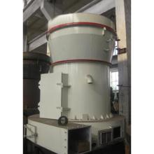
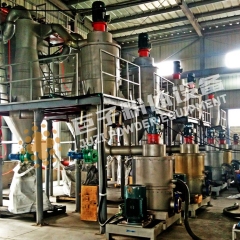
This machine mainly consists of a main unit, a fineness analyzer, a blower, a finished product cyclone collector, a bag filter, and connecting air ducts. Auxiliary equipment such as a crusher, elevator, storage bin, electromagnetic vibrating feeder, and electrical control cabinet can be equipped according to user requirements. In the main unit, the grinding roller assembly is suspended on the grinding roller hanger through a crossbeam shaft. The grinding roller hanger is fixedly connected to the main shaft and the scraper holder. A pressure spring presses against the outer end face of the cantilever of the grinding roller bearing housing, using the crossbeam shaft as a fulcrum to force the grinding roller tightly against the inner surface of the grinding ring. When the motor drives the main shaft to rotate through the transmission device, the scraper mounted on the scraper holder rotates synchronously with the grinding roller. The grinding roller rolls along the inner surface of the grinding ring while rotating around its own axis. The motor drives the impeller to rotate through the transmission device. The higher the impeller speed, the finer the powder separated.
Grinding millWorking process: After large pieces of material are crushed, they are transported to the storage hopper by an elevator, and then continuously and evenly fed into the main grinding chamber by a vibrating feeder. The material entering the grinding chamber is lifted by a shovel blade and crushed between the grinding roller and the grinding ring through rolling and grinding. A blower blows air from around the machine base into the grinding chamber, carrying the crushed material into the analyzer. Large particles fall back for re-grinding, while qualified fine powder flows with the airflow into the finished product cyclone collector. After the fine powder is separated from the air, it is discharged from the discharge port as the finished product. The air then returns to the blower from the upper part, repeating the above cycle.
In the grinding chamber, due to a certain moisture content in the material being ground, heat generated during the grinding process causes water vapor to evaporate. Additionally, the loose connections of various pipes in the entire machine allow external air to be drawn in, increasing the circulating airflow volume. To ensure the mill operates under negative pressure, the increased airflow is discharged through the residual air pipe between the fan and the main machine into the bag filter, where it is purified before being released into the atmosphere.
IV. Installation and Connection
1. When constructing the factory building, it should be considered that a lifting tool capable of hoisting 1.5-2 tons can be suspended above the main unit for maintenance purposes.
2. The main unit and the blower must be placed horizontally on a reinforced concrete foundation (YGM65, YGM75, and YGM85 models may be placed without reinforcement).
The cyclone powder collector and dust collector can be installed by digging pits under their support legs and pouring concrete after the equipment is in place.
3. During installation, sealing gaskets must be added between the flanges of all connecting pipes to ensure a tight seal, and no air leakage is allowed.
V. Usage and Operation
Before starting the mill, check whether there are foreign objects such as iron blocks inside, close the large and small observation doors tightly, adjust the rotation direction of the fan and the main machine, and ensure the exhaust valve is in the fully open position. Check whether the bolts and nuts are loose, with special attention to those inside the main machine.
The startup sequence is as follows: first, start the analyzer, then the fan, followed by the main machine. Immediately after starting the main machine, feed material should be added (first add fine particles, then material of normal particle size). Then, open the air volume valve fully and gradually close the exhaust valve. The exhaust valve should be closed as much as possible while ensuring that the feed material does not spray outward. Next, adjust the fineness of the finished product.
When shutting down, first stop the feeding for about one minute before stopping the main machine, then stop the fan, and finally stop the analyzer.
Feed Control: The feeding should be uniform, and the **output** should be tested based on the load of the main machine under different feeding amounts (observe the main machine's ammeter). It is strictly prohibited for bolts or other iron objects to enter the machine.
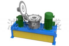
YGM65 and YGM75 Analyzer Fineness Adjustment: Moving the V-belt upward simultaneously on both the large and small stepped pulleys can adjust the analysis impeller.
As the rotational speed increases, the fineness of the finished product becomes finer, and vice versa, it becomes coarser. Moving the motor down by one bolt hole position yields another set of speed levels. The YGM65 and YGM75 models have three speed levels in total. The rotational speed of the YGM85 analyzer can be continuously adjusted within the range of 120 to 1,200 revolutions per minute.
The shorter the compressed length of the pressure spring, the greater the pressure the grinding roller exerts on the material, resulting in higher output. However, the compression should be gradually adjusted based on the main motor load as the grinding roller wears down, ensuring the main motor does not exceed its load capacity. The compressed height of the spring must be greater than 145 millimeters.
6. Maintenance and Care
All bearings are lubricated with No. 1 MOS2 grease or ZN-2 sodium-based grease. The grinding roller shaft is lubricated once per shift, the main machine center shaft bearing is lubricated once every four shifts, and the blower bearing is lubricated once a month. The temperature rise of the bearing housing **must not exceed 70°C**. If the bearing overheats, it should be disassembled, and the bearing, bearing housing, and other accessories should be cleaned once.
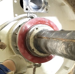
During assembly and disassembly, attention should be paid to the two round nuts at the lower end of the main shaft of the main unit: the one in contact with the V-belt pulley has left-hand threads, while the outer one has right-hand threads. The grinding roller bearings use two radial thrust tapered roller bearings. Therefore, during installation, the thickness of the gasket between the end cover and the bearing housing end face should be adjusted to ensure a reasonable axial clearance (0.25~0.35) for the bearings.
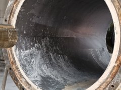
| Function Introduction: 1. No oil leakage, no need to refuel every shift; only a small amount of lubricant needs to be added once every three days to a week. |