- Products
-
Shops
AI Search

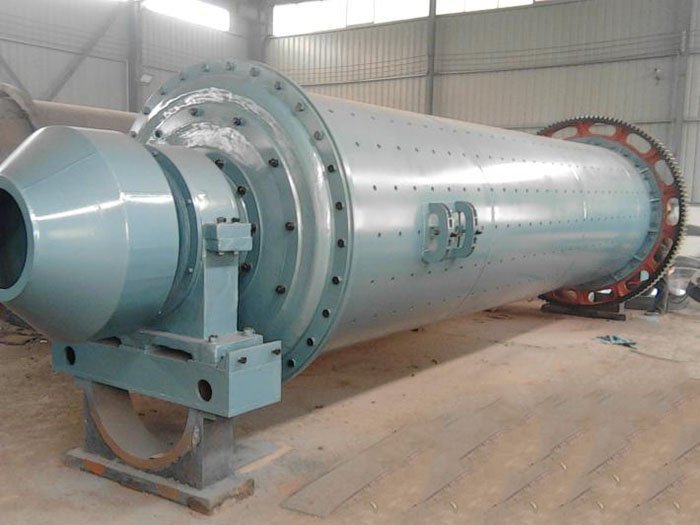
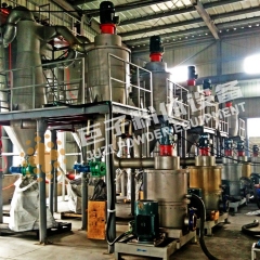
A ball mill is a key equipment for further grinding after materials have been crushed. It is widely used in industries such as cement, silicate products, new building materials, refractory materials, fertilizers, ferrous and non-ferrous metal beneficiation, as well as glass and ceramics. It is employed for dry or wet grinding of various ores and other grindable materials.
The ball mill is mainly composed of the feeding part, discharging part, rotating part, and transmission part (reducer, small transmission gear, motor, electric control), among other key components. The hollow shaft is made of cast steel, with a replaceable inner lining. The large rotating gear is processed by gear hobbing on castings, and the cylinder is lined with wear-resistant plates, ensuring excellent wear resistance. This machine operates smoothly and reliably.
| Energy Saving By matching the energy consumption of the drive and the grinding process, significant energy savings can be achieved. | The design of the discharge section is flexible. The discharge port is reasonably designed, allowing customers to optionally equip a magnetic separator according to their own needs. |
| Rotary Section The cylinder, lining plates, grinding media, partition plates, and discharge grate plates of the rotary section are all assembled using high-quality components. | Large feeding volume in the feeding section. A reasonable feed inlet design increases the feeding volume. |
| High grinding efficiency, good liner quality. The liners and grinding media are made of alumina ceramic, quartz, SILEX, or special materials, with an iron-free contamination design for hard minerals. | Adopting a closed system to reduce dust. The ultra-fine ball mill and classifier form a closed system with negative pressure conveying, ensuring no dust and minimizing harm to the human body. |
Based on the material and discharge method, either a dry ball mill or a wet grid-type ball mill can be selected.
This machine is a horizontal cylindrical rotating device with external gear transmission, featuring two chambers and a lattice-type ball mill. Materials are evenly fed into the first chamber of the mill through the feeding device via the hollow shaft spiral. This chamber is equipped with step liners or corrugated liners and contains steel balls of various specifications. The rotation of the cylinder generates centrifugal force, lifting the steel balls to a certain height before they fall, thereby impacting and grinding the materials. After coarse grinding in the first chamber, the materials pass through a single-layer partition plate into the second chamber. This chamber is lined with flat liners and contains steel balls for further grinding of the materials. The powdered material is discharged through the discharge grate plate, completing the grinding process.
| Specifications and Model | Cylinder rotation speed (r/min) | Amount of balls loaded (t) | Feed particle size (mm) | Discharge particle size (mm) | Output (t/h) | Motor power (kw) | Total weight (t) |
| Ф900×1800 | 36-38 | 1.5 | ≤20 | 0.075-0.89 | 0.65-2 | 18.5 | 5.5 |
| Ф900×3000 | 36 | 2.7 | ≤20 | 0.075-0.89 | 1.1-3.5 | 22 | 6.7 |
| Ф1200×2400 | 36 | 3 | ≤25 | 0.075-0.6 | 1.5-4.8 | 30 | 12 |
| Ф1200×3000 | 36 | 3.5 | ≤25 | 0.074-0.4 | 1.6-5 | 37 | 12.8 |
| Ф1200×4500 | 32.4 | 5 | ≤25 | 0.074-0.4 | 1.6-5.8 | 55 | 13.8 |
| Ф1500×3000 | 29.7 | 7.5 | ≤25 | 0.074-0.4 | 2-5 | 75 | 16.8 |
| Ф1500×4500 | 27 | 11 | ≤25 | 0.074-0.4 | 3-6 | 110 | 21 |
| Ф1500×5700 | 28 | 12 | ≤25 | 0.074-0.4 | 3.5-6 | 130 | 25.8 |
| Ф1830×3000 | 25.4 | 11 | ≤25 | 0.074-0.4 | 4-10 | 130 | 29 |
| Ф1830×4500 | 25.4 | 15 | ≤25 | 0.074-0.4 | 4.5-12 | 155 | 35.5 |
| Ф1830×6400 | 24.1 | 21 | ≤25 | 0.074-0.4 | 6.5-15 | 210 | 43 |
| Ф1830×7000 | 24.1 | 23 | ≤25 | 0.074-0.4 | 7.5-17 | 245 | 43.8 |
| Ф2100×3000 | 23.7 | 15 | ≤25 | 0.074-0.4 | 6.5-36 | 155 | 34.8 |
| Ф2100×4500 | 23.7 | 24 | ≤25 | 0.074-0.4 | 8-43 | 245 | 38 |
| Ф2100×7000 | 23.7 | 26 | ≤25 | 0.074-0.4 | 8-48 | 280 | 56.6 |
| Ф2200×4500 | 21.5 | 27 | ≤25 | 0.074-0.4 | 9-45 | 280 | 51.8 |
| Ф2200×6500 | 21.7 | 35 | ≤25 | 0.074-0.4 | 14-26 | 380 | 60 |
| Ф2200×7000 | 21.7 | 35 | ≤25 | 0.074-0.4 | 15-28 | 380 | 62 |
| Ф2200×7500 | 21.7 | 35 | ≤25 | 0.074-0.4 | 15-30 | 380 | 64.8 |
| Ф2400×3000 | 21 | 23 | ≤25 | 0.074-0.4 | 7-50 | 245 | 54 |
| Ф2400×4500 | 21 | 30 | ≤25 | 0.074-0.4 | 8.5-60 | 320 | 65 |
| Ф2700×4000 | 20.7 | 40 | ≤25 | 0.074-0.4 | 12-80 | 380 | 94 |
| Ф2700×4500 | 20.7 | 48 | ≤25 | 0.074-0.4 | 12-90 | 480 | 102 |
| Ф3200×4500 | 18 | 65 | ≤25 | 0.074-0.4 | Determined according to process conditions | 800 | 137 |
| Ф3600×4500 | 17 | 90 | ≤25 | 0.074-0.4 | Determined according to process conditions | 850 | 158 |
| Ф3600×6000 | 17 | 110 | ≤25 | 0.074-0.4 | Determined according to process conditions | 1250 | 175 |
| Ф3600×8500 | 18 | 131 | ≤25 | 0.074-0.4 | 45.8-256 | 1800 | 252 |
| Ф4000×5000 | 16.9 | 121 | ≤25 | 0.074-0.4 | 45-208 | 1500 | 203 |
| Ф4000×6000 | 16.9 | 146 | ≤25 | 0.074-0.4 | 65-248 | 1600 | 218 |
| Ф4000×6700 | 16.9 | 149 | ≤25 | 0.074-0.4 | 45-252 | 1800 | 238 |
| Ф4500×6400 | 15.6 | 172 | ≤25 | 0.074-0.4 | 54-306 | 2000 | 280 |
| Ф5030×6400 | 14.4 | 216 | ≤25 | 0.074-0.4 | 68-386 | 2500 | 320 |
| Ф5030×8300 | 14.4 | 266 | ≤25 | 0.074-0.4 | 88-500 | 3300 | 403 |
| Ф5500×8500 | 13.8 | 338 | ≤25 | 0.074-0.4 | 108-615 | 4500 | 525 |