
- Products
-
Shops
AI Search

Forced classifier with secondary air intake and vertically mounted large impeller rotor. During operation, materials enter through the lower cylinder under the suction force of the induced draft fan. The external primary air fully mixes with the materials, causing the particles to disperse thoroughly and rise to the classification zone. Due to the high-speed rotation of the classification impeller rotor, the particles are subjected to both the centrifugal force generated by the rotation of the classification impeller and the centripetal force generated by the suction of the induced draft fan. When the centrifugal force acting on the particles exceeds the centripetal force, coarse particles larger than the classification diameter are thrown to the inner wall of the cylinder, lose speed, and slide down along the wall. The external secondary air enters through evenly distributed air inlets on the cone, creating an air-screening effect on the coarse particles to separate and clean the fine powder mixed or adhered to the coarse material. The separated coarse material is collected and discharged by the discharge device, while the fine powder smaller than the classification diameter enters the cyclone collector and pulse dust collector with the gas-solid two-phase flow for collection. The purified gas is then discharged by the induced draft fan.
Main Features:
1、The classifier structure has been specially designed to almost completely block all large particles, ensuring high classification accuracy and strict control over large particles.
2、The classification point can be freely adjusted through the rotational speed of the classifying impeller and the air volume of the induced draft fan to achieve the desired product, offering a wide classification range.
3、The vertical single-impeller classification structure with low rotational speed ensures a stable material flow field, resulting in high processing capacity and efficient classification.
4、A multi-stage series structure can be adopted to simultaneously classify several particle size segments, achieving an ideal particle size distribution.
Process Flow Diagram![]()
![]()
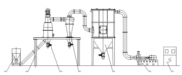
![]()
1hopper 2Operating Platform 3Classifier 4Cyclone collector
5Pulse dust collector 6High-pressure induced draft fan 7, electric control cabinet
Specifications:
Specifications and Models | Processing capacity(kg) | Classification efficiency%) | Product granularity(um) | Matching power (kw) |
FJ350 | 500~1000 |
70~90
|
D97=5~45 | 30 |
FJ400 | 800~2500 | 50 | ||
FJ450 | 2000~4000 | 75 | ||
FJ550 | 4000~7800 | 112 | ||
FJ650 | 6500~12000 | 140 | ||
FJ800 | 8000~17000 | 169 | ||
FJ900 | 10000~22000 | 205 | ||
FJ1000 | 13000~26000 | 240 |


